Induction furnaces in industry have two main applications: melting and heat treatment. Induction melting furnaces are primarily used for melting metals such as steel, cast iron, gold, copper, and aluminum. It is worth noting that in the steel industry, induction melting furnaces are used both for casting component manufacturing and in steelmaking industries.
Induction melting furnaces are widely used in industries producing stainless steel, steel, cast iron, copper, aluminum, brass, bronze, and gold components. The advantages of using induction furnaces over other furnace types depend on the specific application and desired product.
Steelmaking:
Steelmaking is primarily produced using a combination of steel scrap, along with sponge iron, and electric arc furnaces or induction furnaces. Generally, for the production of alloy steels, especially in capacities less than 300,000 tons per year, the best, and sometimes the only industrially justifiable method, is the use of induction furnaces. On the other hand, in steelmaking industries with capacities of several million tons per year, electric arc furnaces are more economical and justifiable than other methods.
It is important to note that in induction furnaces, alloying can be done in one step. In other words, in an induction furnace, the required alloy is made in one step during or at the end of melting, while in arc furnaces, alloying is done in separate processes after the melt is prepared.
Foundry:
Foundry industries are involved in the construction of metal parts with a very wide range of alloys. Today, many of the components used in devices are made of cast iron, steel, aluminum, copper, bronze, etc., which are mainly produced by casting. In the past, fossil fuel furnaces were widely used for melting metals in foundry industries, but today, due to the numerous advantages of induction furnaces, these models have replaced old models. The characteristics of induction furnaces include:
- High melting speed
- Reduced waste losses during melting
- Control of melting temperature
- Ability to melt metals with high melting points
- Ability to produce required alloys
- Reduced energy consumption
- Reduced environmental pollution
Heat treatment:
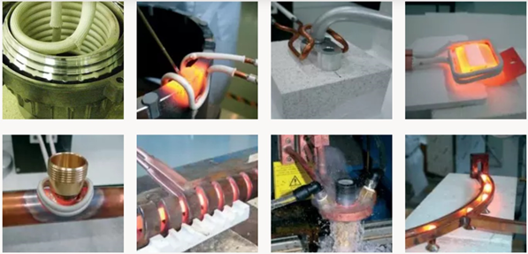
In the process of manufacturing metal parts for machinery, in addition to casting, sometimes other operations are also required, which can be easily achieved with high accuracy, energy concentration, and high efficiency using induction heating systems. Some of these operations can be listed as follows:
- Bending: Heating pipes or metal shafts to form metals with speed, accuracy, and fully controlled by induction heaters is possible.
- Stress relief: Induction heaters and flexible coils are used to heat the welding locations in pipes and metal sheets.
- Hardening: Hardening operations for any depth and degree of hardness and for any geometric shape are possible with induction systems.
- Roll forging: The production of steel balls by roll forging is done on a large scale using induction heaters to heat steel billets.
- Bearing replacement and installation: Heating bearings or different bushings for assembly or disassembly in various cases, including replacing the bearings of rolling mill shelves, with high accuracy and speed without damaging the main parts, is possible using induction systems.
- Preheating: Preheating billets, steel billets, or slabs before forging or rolling with controlled speed and minimizing surface oxidation can be achieved with induction systems.
- Pipe cladding: In the process of cladding spiral pipes, the pipe is heated using an induction heater.
- Annealing: Currently, annealing pipes and copper and brass profiles with the desired speed, high accuracy, and control of the required annealing range is done using induction heaters as the best controllable tool.
History
Hans Christian Ørsted, a Danish physicist (1777-1851), discovered that an alternating magnetic field is formed around a wire carrying an alternating electric current. This very important discovery was the beginning of what scientists like Michael Faraday (1791-1867) and James Clerk Maxwell (1831-1879) completed, ultimately leading to Faraday’s equations and Maxwell’s equations.
In short, it can be said that the discovery, analysis, and understanding and utilization of the relationship between electricity and magnetic fields opened a new door to the world. With the discovery of these relationships, in addition to understanding and analyzing many phenomena in the world, the possibility of building new devices and equipment was also made available to humans.
Modern humans pass so easily by equipment such as electric motors, transformers, induction furnaces, and thousands of other products, as if they had been available to humans since the beginning of history. However, history shows that the modern world and all the facilities available to humans are indebted to the curiosity, hard work, sacrifice, and selflessness of various scientists, each of whom in their lifetime, both short and long, has dedicated pages of history to themselves.
A summary of history in a glance shows the evolution of science and the invention of some very useful products that the world would have been different without today:
- Invention of the battery by Alessandro Volta, 1800
- Discovery of the magnetic field around a current-carrying conductor by Ørsted, 1820
- Faraday’s Law, 1831
- Invention of the induction motor by Peter Barlow, 1834
- Invention of the transformer by William Stanley, 1885
- Invention of the induction furnace by Edward Allen Colby, 1900
How Induction Furnaces Work
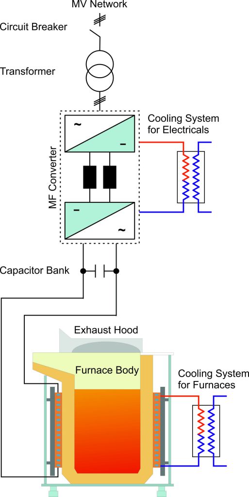
The operation of induction furnaces is explained based on phenomena that occur when metal and a magnetic field are in proximity. In this way, the passage of alternating electric current in a conductor causes a magnetic field to be created around it, and the presence of metal in the vicinity of this field causes the field to penetrate the conductor and create eddy currents in it. Corresponding to the formed eddy current and the electrical resistance of the metal, thermal losses are created in it, causing it to heat up or, in other words, generate heat in the metal.
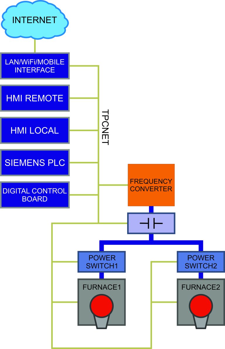
The heat generated in the metal practically shows that electrical energy has been converted to magnetic energy and induced in the metal, and then again converted to electrical energy and finally to thermal energy. The amount of heat generated, or in other words, the power consumption of the device, depends on various parameters that must be controlled to control the operation and power consumption of the device. In the following, the factors affecting the device’s power and the methods of controlling them, which ultimately lead to controlling the device’s power, as well as the components of the induction furnace from an operational perspective, are briefly introduced:
Induction Coil
Strengthening the magnetic field, focusing the field, guiding the magnetic field in a range where heating needs to be created, controlling the amount of heating generated, adapting the absorption capacity according to the application of the device and the power required to generate heat, are some of the functions of the induction coil. The induction coil is essentially a concentrator of the field in a location where heating needs to be created. Here are some examples of induction coils:
- Induction Coil in Melting Furnaces Melting induction coils are made in a helical shape. In coil design, considering the melting capacity, device power, and operating frequency, three main parameters are calculated for its construction: diameter, height (length), and number of turns. These calculations are the most important step to start designing, and considering the default data resulting from previous experience in coil design, the feasibility of the design and its optimization, after the initial design, is very important in finalizing the coil design.
The Company (you can replace this with the actual name of the company) classifies its melting furnaces from 500 kg to 30 tons according to the table below and designs and implements melting induction coils based on the parameters mentioned in the table. It is worth noting that this company, due to its design and engineering office, is able to simulate, review, and optimize all melting coils.

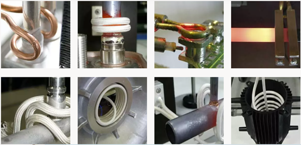
- Induction Coils in Heat Treatment Furnaces The range of applications for induction furnaces as a heat source in various industries is vast. Induction systems have many diverse applications, and consequently, the induction coils used are also highly diverse in terms of shape, size, and usage. In other words, by leveraging the capabilities of induction systems, it’s possible to design a coil shape that concentrates energy in the required area to generate heat in any metal with any geometric shape. Below are some examples of coils with different geometric shapes for various applications:
Capacitor Bank In practice, the equivalent circuit of an induction coil can be represented as a combination of resistance and inductance, taking the following form:
XL = R + jLω
In all induction coils, the power factor is very small, so in practice, the power supply connected to the coil cannot transfer a significant amount of active power compared to the reactive power transferred. To address this issue, a capacitor bank is always used to compensate for the reactive power of the induction coil. Therefore, the equivalent circuit of the entire assembly can be simplified as:
X = R + jLω – j/(Cω)
To eliminate reactive power, the capacitance of the capacitor bank must be equal to the reactance of the inductor (coil):
jLω = j/(Cω)
This results in a resonance at the resonant frequency:
ω = 2πf
In this situation, the equivalent circuit of the capacitor bank, coil, and load can be considered resistive, meaning that reactive power is not transferred to the power supply. In many applications of induction systems, the load is variable, and changes in the load lead to changes in the inductance of the induction coil. The capacitor bank, however, is considered constant, and therefore the resonant frequency will vary.
Beyond the coil current, the amount of reactive power eliminated, or impedance matching between the load and the power supply, plays a key role in the power transfer from the power supply to the coil. The above descriptions suggest that the power supply connected to the induction coil will have variable and controllable parameters that not only assist in impedance matching but also control the power absorbed by the load.
The capacitor bank for impedance matching and reactive power elimination can be connected to the coil in series or parallel configurations. These arrangements are referred to as series resonance and parallel resonance respectively.
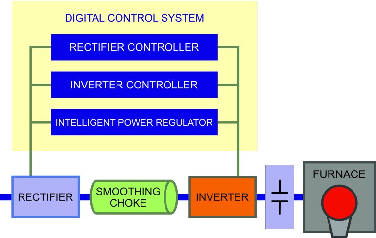
Power Supply The power supply in induction systems consists of two distinct parts. The first part is a converter that converts alternating current (AC) to direct current (DC), known as a rectifier. The output from this part is independent of the input AC frequency, meaning the frequency of the power grid has no effect on its operation. Rectifiers are categorized as controlled and uncontrolled.
The second part of the power supply is a DC-to-AC voltage converter, also known as an inverter, where frequency is the only controllable parameter. Inverters in induction furnace power supplies come in two configurations: VSI (Voltage Source Inverter) and CSI (Current Source Inverter).
VSIs are commonly used for series-resonant furnaces. In these furnaces, the voltage and current of the coil, and ultimately the power, are regulated by changing the frequency of the inverter. The rectifier in the power supply is typically uncontrolled.
CSIs are mainly used for parallel-resonant or series-parallel resonant furnaces. In these furnaces, voltage and current regulation of the coil, and ultimately the power, is achieved by adjusting the output voltage of the rectifier. The frequency is adjusted in a feedback loop to ensure proper impedance matching between the reactive power consumed by the coil and the capacitor bank. Regulating power by changing the rectifier output voltage always introduces some reactive power into the grid, reducing furnace efficiency and increasing energy costs.
In its new generation furnaces, Sepahan Elgha Engineering Company utilizes a parallel resonant arrangement. To enhance melting speed, improve efficiency, reduce energy consumption, minimize grid harmonics, and eliminate reactive power in the grid, the company employs an Intelligent Power Regulator (IPR) system. This system dynamically adjusts impedance matching between the load and the power source during the melting process, enabling maximum power transfer to the load.
