In an induction furnace, a large current with a frequency close to 1000 Hz is induced inside the coil, enabling the melting process.
The inverter is responsible for supplying the appropriate current with adjustable frequency.
It converts the direct current (DC) supplied by the rectifier circuit into single-phase alternating current (AC).
The diagram below depicts the functional diagram of the induction melting system.
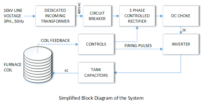
3 Phase Controlled Rectifier
The initial stage in this AC-DC-AC design is the AC-DC conversion, performed by a three-phase bridge rectifier. The semiconductor devices (SCRs) function as electrical check valves, permitting current flow in only one direction. The output of the three-phase bridge is a DC voltage featuring the characteristic 300 Hz ripple of a three-phase full-wave rectifier.
DC Choke
Filtering of the three-phase bridge output is implemented in the DC link between the rectifier and the inverter input. This function is performed by the filter reactor (DC choke). The DC choke serves to mitigate the adverse effects of high-frequency current ripple on the input line as well. Additionally, the DC choke limits the di/dt (current rise rate) during inverter-side short-circuit faults, thereby enhancing the effectiveness of the protection circuitry.
Inverter
In this system, the inverter – composed of semiconductor (SCR) elements – operates by switching at a frequency near the resonance frequency of the LCR tank circuit (formed by the coil and capacitors). This creates “resonance” phenomena, enabling the generation of output voltages significantly higher than the input voltage.
Resonance
In practice, the equivalent circuit of an induction coil can be represented as a combination of resistance and inductance, taking the following form:
XL = R + jLω
In all induction coils, the power factor is very small, so in practice, the power supply connected to the coil cannot transfer a significant amount of active power compared to the reactive power transferred. To address this issue, a capacitor bank is always used to compensate for the reactive power of the induction coil. Therefore, the equivalent circuit of the entire assembly can be simplified as:
X = R + jLω – j/(Cω)
To eliminate reactive power, the capacitance of the capacitor bank must be equal to the reactance of the inductor (coil):
jLω = j/(Cω)
This results in a resonance at the resonant frequency:
ω = 2πf
In this situation, the equivalent circuit of the capacitor bank, coil, and load can be considered resistive, meaning that reactive power is not transferred to the power supply. In many applications of induction systems, the load is variable, and changes in the load lead to changes in the inductance of the induction coil. The capacitor bank, however, is considered constant, and therefore the resonant frequency will vary.
Comment (1)
Comments are closed.
Comparison Of Series And Parallel Induction Furnaces - Sepahan Elgha Co.
July 21, 2025[…] parallel. (If you would like to learn more about the phenomenon of resonance, we recommend reading this article first.) In this article, we will examine the structural and functional differences between these […]